AC80 AC90 AC100 single phase motors. Motor Wiring Diagram DC.
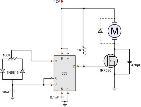 555 Dc Motor Speed Control Motor Speed Circuit Diagram Circuit
The self-excited motors are further classified as Shunt wound or shunt motor Series wound or series motor and Compound wound or compound motor.

Dc motors wiring diagram. E Bike Controller Wiring Diagram - Collections Of E Bike Controller Wiring Diagram List Diagram Electric Bike. DC Permanent Magnet with PWM controller Great for torque at all speeds2 wires to the motor Usually. Vary the voltage applied to the armature vary the speed.
These connections are in accordance with NEMA MG-1 and American Standards Publication 06. Dayton Electric Motors Wiring Diagram dayton 1 hp electric motor wiring diagram dayton 15 hp electric motor wiring diagram dayton electric motor wiring schematic Every electric structure is composed of various distinct pieces. The dc motor converts electrical power into mechanical power.
Each component ought to be set and linked to different parts in particular way. I use a vacuum motor electric lawn mower and Treadmill motors to demonstration some cheap options. If not the arrangement will not function as it should be.
Each component should be set and connected with different parts in particular way. Shop DC Motor Ceiling Fans. A DC motor is by far the preferred motor in many applications today from electric trains to cranes to elevators and are definitely the choice for ceiling fans.
AS-183 wiring diagram with switch. A wiring diagram is a streamlined conventional pictorial representation of an electrical circuit. Great for torque at all speeds4 wires to the motor.
Collection of dc motor wiring diagram 4 wire. Refer to the motor manufacturers data on the motor for wiring diagrams on standard frame Ex e Ex d etc. Inst Maint Wiringqxd 5032008 1002 AM Page 6.
Brushless motors bldc motor 3 phase dc controller wiring diagram 48 volt 1800 watt 350w 2007 mustang brain power change a rotation yamaha sd wphmoto high 48v 1800w schematic 36v electric bicycle e bike sensorless using page 2 esc auto ku63 wire center 48v350w hyperion general ebike of 1000 scooter with 50v driver 24v 250w 72v 1 smart electronic ho to the tamiya control. Two Speed One Winding CHP MS Single Voltage. As the demand for energy-efficient products increases so does the use of DC motors in ceiling fans and other.
Wiring Point-work Special track conditions for DC or DCC A reminder -ALL examples and the things we use for switching such as Cobalt motors Cobalt-S levers and AD or AD-S accessory decoders will work as well on DC as they do on DCC so you can use these diagrams for ANY layout with ANY form of control. 2 run to the shunt-field current 2 run to the armature. Use figure 1 if your motor has a single voltage shunt field.
E Bike Controller Wiring Diagram Recent Wiring Diagram Electric Bike. 4 wire reversible PSC motor. Baldor Motor Wiring Diagram baldor 5hp motor wiring diagram baldor brake motor wiring diagram baldor dc motor wiring diagram Every electrical structure is composed of various diverse parts.
At the bottom of this post is also a video about DC shunt motors. 2018 24v36v48v 250w350w Bldc Motor Speed Controller 6 Mosfet Dual. Advantages of Ceiling Fans with DC Motors.
AC80 AC90 AC100 single phase motors. Some text links below go to applicable products on Amazon and EBay. These diagrams are current at the time of publication check the wiring diagram supplied with the motor.
Where can I find single phase electric motor wiring diagrams. The construction of the dc motor and generator are the same. It reveals the parts of the circuit as streamlined forms as well as the power and signal links between the gadgets.
DC Series Motor Components used in DC Series Motor. 3 Wire Dc Motor Diagram Wiring Diagram Content Build A Versatile Miniature High Rate Esc With Bec And Brake Wphmoto High Speed 48v Dc 1800w Brushless Electric Motor 800w 500w 24v 36v 48v Mofset Brushless Motor Controller E Bike Motor Control Circuit Page 4 Automation Circuits Next Gr 1 Surpass Hobby 2040 3900kv Brushless Motor For 1 20 1 18 1. DC motor with Armature-voltage DC Motor Control.
Motor Connections Your motor will be internally connected according to one of the diagrams shown below. By Sans Aihara On February 24 2021 In Wiring Diagram 180 views Dc Motors And Potentiometers Wiring 4 5 180 votes Top Suggestions Dc Motors And Potentiometers Wiring. Not all 4 wire motors.
I have compiled a group of single phase internal electric motor wiring diagrams and terminal connections below. If not the structure wont work as it should be. Two Speed One Winding VT or CT MS Single Voltage.
The components of this motor mainly include the rotor the armature commutator stator axle field windings and brushesThe fixed component of the motor is the stator and it is built with two otherwise more electromagnet pole parts. 36v 800w Set Electric Bike Controller Twist Throttle Brake Lever. Use figure 2 if your motor has a dual voltage shunt field.
Wiring a DC motor and Universal motor for speed control.
 Dc Motor Braking Circuit Diagram Elec Eng World Circuit Diagram Electrical Motors Circuit
 Dayton Electric Motors Wiring Diagram Download In 2020 Diagram Electrical Circuit Diagram Diagram Chart
 Schematic Wiring Diagram For Dc Electric Motor Connections Electric Motor Electricity Universal Motor
 How To Wire An Electric Motor To Run On Both 110 And 220 Volts Hunker Electric Motor Electricity Circuit Bending
 Full Set Of 48v 1800w Brushless Electric Motor Controller Battery Kit Fr Go Kart Electric Scooter Electric Bike Diy Electric Go Kart